 Join Slack
EVPN on Host
Overview
Traditionally, Software-Defined Networking (SDN) platforms have created virtual overlays on top of physical switch networks, operating with a control plane entirely separate from the switch fabric. These software-defined overlays lack hardware acceleration and cannot provide performance and security guarantees of hardware-level isolation.
AI Cloud and AI Factory operators require
Bare metal servers to have tenant isolation enforced by the network hardware with no dependency on host agents or subinterfaces inside the server OS.
Virtual workloads (VMs, containers, Kubernetes pods) to coexist with bare metal servers in the same tenant VPC, using the same segmentation and security policies.
Starting with Netris 4.5.4, you can extend the EVPN control plane into any standard Linux host, such as a hypervisor or a Kubernetes node, by making the host itself a VTEP in the Netris-managed EVPN switching fabric. With this functionality, any guest workload, such as a VM or a Container pod, can be placed in any VPC and V-Net together with any Bare Metal host.
Supported Operating Systems
The Netris host agent is fully tested and supported on Ubuntu 24.04 LTS.
The agent can also be adapted to run on any modern Linux distribution that supports:
systemd (for managing the agent service)
iproute2 tools (ip, bridge, etc.)
Kernel support for VXLAN
Contact Netris for more information about other operating systems.
Use Cases
Managed Kubernetes
Many major cloud providers offer a Managed Kubernetes service, where tenants consume a Kubernetes cluster without managing its underlying control plane (e.g., Kube API) or infrastructure. While it is necessary to organize multi-tenancy of the Kubernetes API itself, network-level multi-tenancy enforcement is essential to successfully providing a Managed K8S service.
The Kubernetes mechanisms alone are insufficient to achieve this, so the Netris EVPN-on-Host solution delivers the necessary network control plane extensions to the Kubernetes node, enabling you to offer a similar service with seamless integration between virtual and bare metal workloads within the same VPC and V-Net.
In this model:
Netris EVPN-on-Host agent uses standard Linux networking constructs to enforce tenant isolation, so you can securely colocate multiple isolated Kubernetes Control Planes (a.k.a. Master nodes) on the same physical hardware.
Netris-managed EVPN switches continue to enforce tenant isolation for the Bare Metal worker nodes without the need for the host agent.
Other Uses
Netris EVPN-on-Host is a general mechanism for extending V-Nets to any Linux host. It can be used to bridge virtual, container, and bare metal endpoints across a wide range of use cases.
How It Works
Consider the following diagram, which illustrates system behavior after the Netris agent is deployed on an endpoint (mgmt-srv-01).

The diagram shows a shared node (mgmt-srv-01) and two sets of dedicated GPU nodes — one for tenant Red (gpu-node-10) and one for tenant Blue (gpu-node-20). All 3 nodes are connected to the North-South fabric (top), and the 2 GPU nodes are also connected to the East-West fabric (bottom). The Netris Controller manages both fabrics and the host agent on the shared node.
Bare Metal GPU Nodes
Bare Metal GPU nodes remain unmanaged by Netris at the host level. You are responsible for configuring their server NICs (e.g., bond0) while Netris manages only the switch-side configuration.
Underlay Configuration
Netris automatically configures BGP and EVPN on both the switch side and the EVPN-host side when
The server role is set to “EVPN-VTEP”
The host has the Netris-on-Host package installed
The server-to-switch links are configured in “underlay” mode as described later in this document.
Packet Flow

Diagram Legend.
10.188.1.0/24 - Tenant Red subnet.
172.16.0.0/24 - Underlay prefix. Switch and EVPN-hosts VTEP loopback IPs are allocated from this prefix.
mgmt-srv-01 is a hypervisor or a Kubernetes node hosting VMs or containers and runs Netris EVPN-on-Host agent. The host agent enables Netris to extend tenants’ VPCs (VRFs) and V-Nets (VXLANs) into the host and bridge them with tenants’ VMs and containers.
gpu-node-10 is a bare metal host with no Netris software on it. A tenant’s access to this host type is defined through Netris and automatically enforced on the connected leaf switch.
Scenario.
Pod1 (IP: 10.188.1.10) communicates with gpu-node-10 (IP: 10.188.1.200). VXLAN encapsulation and tenant isolation for Pod1 happen on the mgmt-srv-01 node itself. By contrast, encapsulation and tenant isolation for the bare metal node gpu-node-10 happen on the switch.
FRR running on the mgmt-srv-01 node maintains EVPN BGP adjacencies with the directly connected physical leaf switches and exchanges IP/MAC reachability information between mgmt-srv-01 and the physical switches. As a result, all VTEPs, such as mgmt-srv-01 and any leaf switch, know how to reach a given IP/MAC within a given VPC (VRF).
Pod1 (IP: 10.188.1.10) in VPC Red running on node mgmt-srv-01 (where EVPN-on-Host agent is installed) generates a packet destined to node gpu-node-10 (IP 10.188.1.200) also in VPC Red.
The packet hits the tenant’s VXLAN bridge (vxlan1000) on node mgmt-srv-01. The node’s Linux OS encapsulates the original packet as a payload into a VXLAN packet with destination IP 172.16.0.50 (Leaf4 switch loopback IP), source IP 172.16.0.10 (node mgmt-srv-01 loopback IP), and VNI 1000 in the outer header. Then, based on the routing table FRR installed on the node, the packet is sent out of one of the two server NICs (eth9 or eth10, which are ECMP load balanced) connected to Leaf1 and Leaf2 switches.
The receiving leaf switch (e.g., Leaf2) forwards the VXLAN packet to the spine and subsequently to the leaf switch connected to the bare metal node gpu-node-10 (Leaf4) based on the 172.16.0.50 VXLAN packet destination IP address.
The receiving leaf switch Leaf4 decapsulates the payload from the VXLAN packet and sends the original IP packet directly to the bare metal server gpu-node-10.
The bare metal server (g`pu-node-10`) receives the original packet destined to its IP 10.188.1.200, seeing the packet sourced from Pod1 (IP: 10.188.1.10).
Conversely, when gpu-node-10 sends a packet to Pod1, the process happens in reverse order.
gpu-node-10 originates a packet with source IP 10.188.1.200 (bond0) and destination IP 10.188.1.10 (Pod1).
The original packet, based on LACP load balancing, if configured, is received by one of the directly connected leaf switches (Leaf3 or Leaf4) from the bare metal host gpu-node-10.
The receiving leaf switch (e.g., Leaf4) encapsulates the original packet into a VXLAN packet with source IP address as self (e.g., 172.16.0.50), destination IP address of mgmt-srv-01 (172.16.0.10), VNI 1000, then forwards it into the EVPN fabric.
The EVPN fabric routes the VXLAN packet to mgmt-srv-01 based on destination IP 172.16.0.10 (the mgmt-srv-01 loopback and VTEP IP).
mgmt-srv-01, running the EVPN-on-Host Netris agent, decapsulates the VXLAN packet and forwards the original packet to Pod1 via vxlan1000 bridge interface.
Management Plane
A management V-Net is used to enable a variety of management flows, including
The initial server provisioning (e.g., PXE boot),
Various ongoing administration tasks (e.g., SSH access and monitoring),
The Netris agent’s installation and subsequent communication with the Netris controller.
Initially, before the EVPN-on-Host agent is installed, you assign the management IP to the server’s NIC (e.g., mgmt-srv-01 eth9).

Diagram Legend.
172.16.0.0/24 - Prefix from which VTEP IPs are allocated.
192.168.5.0/24 - Management subnet VNI 60.
10.200.50.0/24 - Infrastructure subnet where the Netris Controller is hosted. VNI 70.
Once the Netris EVPN-on-Host agent is installed and able to communicate with the Netris controller, the agent creates a VXLAN bridge (e.g., vxlan50 in the following diagram) for the management V-Net, configures FRR, and attempts to initiate EVPN BGP sessions with the directly connected leaf switches. The sessions will remain down until the user instructs the system by enabling the underlay mode on the switch-to-server links.
When you enable the underlay mode on one or both of the switch-to-server links in the Netris controller, an EVPN BGP session per enabled link is established as a result. An ESTABLISHED EVPN BGP session triggers the Netris agent to automatically transfer the management IP (192.168.1.10/24) and the associated default route from the server’s NIC to the VXLAN bridge. This action keeps the server reachable via the same management IP. Without this action, the IP directly configured on a NIC would become inaccessible due to the switch-to-server links switching to the EVPN/VXLAN mode.

Tip
The agent will keep the management IP on the VXLAN bridge interface as long as at least one EVPN BGP session is in the ESTABLISHED state.
The agent will return the management IP to the server NIC if none of the EVPN BGP sessions are in the ESTABLISHED state.
This behavior makes it possible to maintain connectivity through the management interface during both operational states: regular Ethernet and EVPN/VXLAN-based.
It may take up to 2 minutes for the IP to be transferred to the appropriate interface after the BGP state change.
Prerequisites
For the EVPN-on-host solution to operate correctly, the following prerequisites must be in place before installing the Netris host agent.
1. Management V-Net
The management V-Net is for the systems administrator, the Netris Controller, and various support systems to reach the host for a variety of administrative use cases, including
The initial server provisioning (e.g., PXE boot),
Various ongoing administration tasks (e.g., SSH access and monitoring),
The Netris agent’s installation
The Netris agent’s communication with the Netris controller.
In this V-Net, you must
Include the switch ports (directly, using labels, or through Server Cluster) to which the EVPN-on-Host candidate servers are connected in the North-South fabric as untagged.
Warning
The switch ports must be added to the management V-Net as untagged. The untagged property of the switch port signals the system to configure the management V-Net gateway on the switch rather than on the host itself. By contrast, when tenants’ V-Nets are provisioned on the host, as described later in this document, the same switch ports are added to the tenant’s V-Nets as tagged, which signals the system to configure the gateway IP for those V-Nets on the host’s VXLAN bridge interface.
2. Server Objects
The server object (in Inventory) representing the server, which will run the EVPN-on-Host agent, must be set to role EVPN-VTEP.
3. Server Networking Configuration
The physical server must be configured with a management IP address that is able to communicate with the Netris Controller.
4. Netris Controller
The Netris Controller must be reachable from the Management V-Net for proper agent installation and subsequent operational communication.
Installation
Install the EVPN-on-Host agent
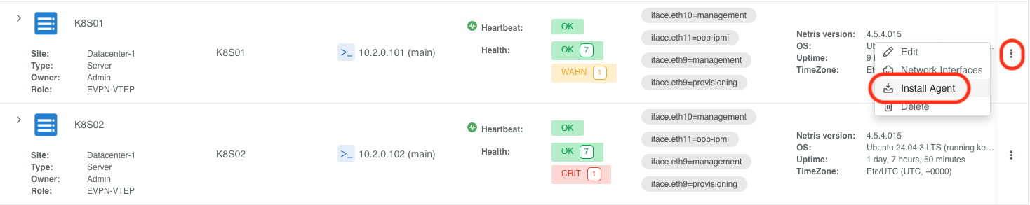
Navigate to Network → Inventory, locate the subject node in the list, and click the 3-dot menu for the subject host and select Install Agent.
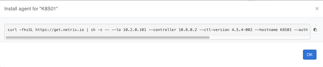
Copy the one-liner command and paste it into the server’s CLI.
Once the agent installation is complete, reboot the server.
Enable Underlay
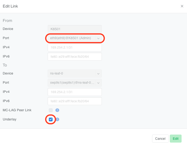
Navigate to Network → Topology and enable the Underlay option on the appropriate server links.

Once you enable the Underlay property, the EVPN-on-Host agent will automatically transfer the management IP to the VXLAN bridge interface within a minute.
Verification
Once the agent installation is complete, check the connectivity, and you should see the mgmt bridge with name nbr-<VXLAN ID OF VNET>
root@K8S01:~# ip -4 a
1: lo: <LOOPBACK,UP,LOWER_UP> mtu 65536 qdisc noqueue state UNKNOWN group default qlen 1000
    inet 127.0.0.1/8 scope host lo
    valid_lft forever preferred_lft forever
    inet 10.2.0.101/32 scope global lo
    valid_lft forever preferred_lft forever
7: nbr-14: <BROADCAST,MULTICAST,UP,LOWER_UP> mtu 1500 qdisc noqueue state UP group default
    inet 10.12.0.101/16 brd 10.12.255.255 scope global nebrvx-14
    valid_lft forever preferred_lft forever
There should be a new default route present via the management bridge.
root@K8S01:~# ip r
default via 10.12.0.1 dev nbr-14
Tip
You can verify BGP and EVPN adjacencies using the FRR’s show bgp summary command
root@K8S01:~# vtysh -c 'show bgp summary'

IPv4 Unicast Summary:
BGP router identifier 10.2.0.101, local AS number 4200000001 VRF default vrf-id 0
BGP table version 33
RIB entries 23, using 2944 bytes of memory
Peers 2, using 47 KiB of memory

Neighbor        V         AS   MsgRcvd   MsgSent   TblVer  InQ OutQ  Up/Down State/PfxRcd   PfxSnt Desc
ns-leaf-0(ens4) 4 4200300001      6909      6933       33    0    0 05:27:21           10       12 N/A
ns-leaf-1(ens5) 4 4200300002      6926      6932       33    0    0 05:27:18           10       12 N/A

Total number of neighbors 2

L2VPN EVPN Summary:
BGP router identifier 10.2.0.101, local AS number 4200000001 VRF default vrf-id 0
BGP table version 0
RIB entries 137, using 17 KiB of memory
Peers 2, using 47 KiB of memory

Neighbor        V         AS   MsgRcvd   MsgSent   TblVer  InQ OutQ  Up/Down State/PfxRcd   PfxSnt Desc
ns-leaf-0(ens4) 4 4200300001      6909      6933       39    0    0 05:27:21          146      227 N/A
ns-leaf-1(ens5) 4 4200300002      6926      6932       39    0    0 05:27:18          141      227 N/A

Total number of neighbors 2
Provisioning Tenants
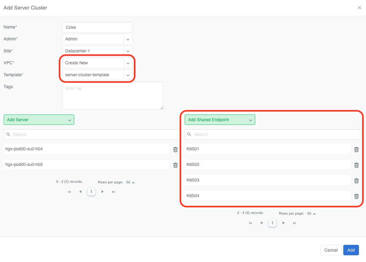
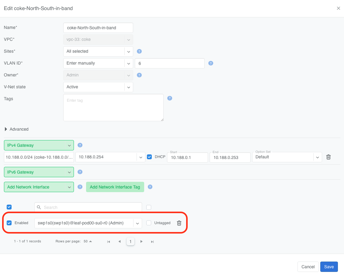
To provision a tenant’s V-Net on an EVPN-on-Host enabled server, add the switch ports connected to the EVPN-on-Host server to the tenant’s V-Net as tagged ports using any of the supported methods:
Add this node as a Shared Endpoint to that tenant’s Server Cluster.
Or add the appropriate switch ports to the V-Net using label.

Or add the appropriate switch ports to the V-Net directly.
Verification
Netris automatically configures the V-Net gateway to reside on each managed host for every tenant V-Net.
root@K8S01:~# ip -4 a
1: lo: <LOOPBACK,UP,LOWER_UP> mtu 65536 qdisc noqueue state UNKNOWN group default qlen 1000
    inet 127.0.0.1/8 scope host lo
    valid_lft forever preferred_lft forever
    inet 10.2.0.101/32 scope global lo
    valid_lft forever preferred_lft forever
2: ens4: <BROADCAST,MULTICAST,UP,LOWER_UP> mtu 1500 qdisc fq_codel state UP group default qlen 1000
    altname enp0s4
    inet 10.254.254.10/24 brd 10.254.254.255 scope global dynamic ens4
    valid_lft 172611sec preferred_lft 172611sec
7: nbr-14: <BROADCAST,MULTICAST,UP,LOWER_UP> mtu 1500 qdisc noqueue state UP group default
    inet 10.12.0.101/16 brd 10.12.255.255 scope global nbr-14
    valid_lft forever preferred_lft forever
9: nbr-26: <BROADCAST,MULTICAST,UP,LOWER_UP> mtu 1500 qdisc noqueue state UP group default
    inet 10.188.0.254/24 brd 10.188.0.255 scope global nbr-26
    valid_lft forever preferred_lft forever
17: nbr-31: <BROADCAST,MULTICAST,UP,LOWER_UP> mtu 1500 qdisc noqueue state UP group default
    inet 10.188.1.254/24 brd 10.188.1.255 scope global nbr-31
    valid_lft forever preferred_lft forever