 Join Slack
Netris VPC
The Netris VPC offers you the ability to operate your resources within a logically segregated virtual network. You can create, edit, and remove VPCs as needed. The VPC acts as a VRF in traditional networking, providing the flexibility to employ overlapping IP ranges across various VPCs while maintaining secure management and operation of resources.
Netris Controller ships with one VPC (VPC-1) pre-provisioned; it cannot be deleted. VPC-1 carries two distinct roles at once — it is both the System VPC (the trust boundary and anchor for infrastructure objects such as switch loopbacks and SoftGate-terminated BGP/NAT/load-balancer traffic) and the Default VPC (the VPC the Controller substitutes for the required VPC field when a value isn’t explicitly given, and the one pre-populated in “Add new” dialogs in the web UI). These are different concepts that happen to be the same VPC by default. See the Netris VPC page for the full explanation and for the list of objects that belong to a VPC, before creating additional VPCs.
The following diagram shows a VPC concept in the Netris Controller.
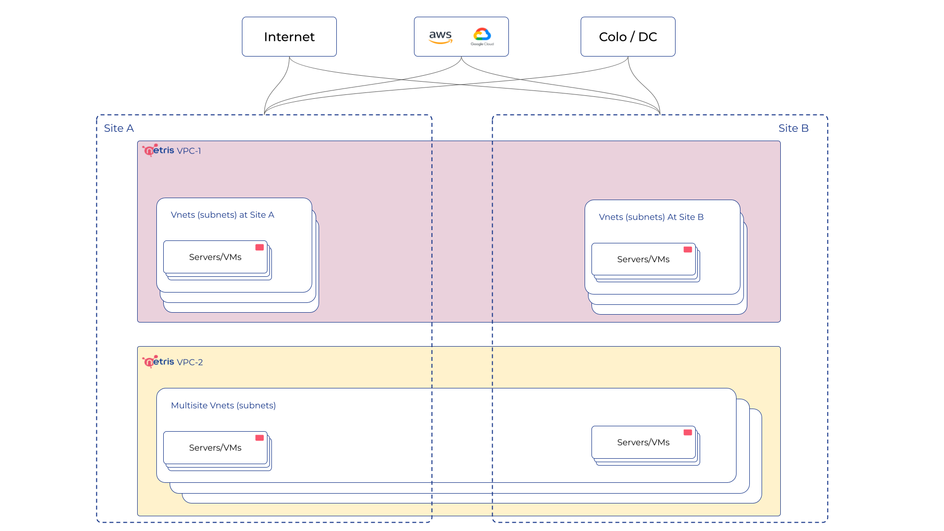
VPC is the highest entity in the hierarchy and it spreads over all Sites. Take a look at the VPC features and services.
VPC can be created in the Network → VPC section.
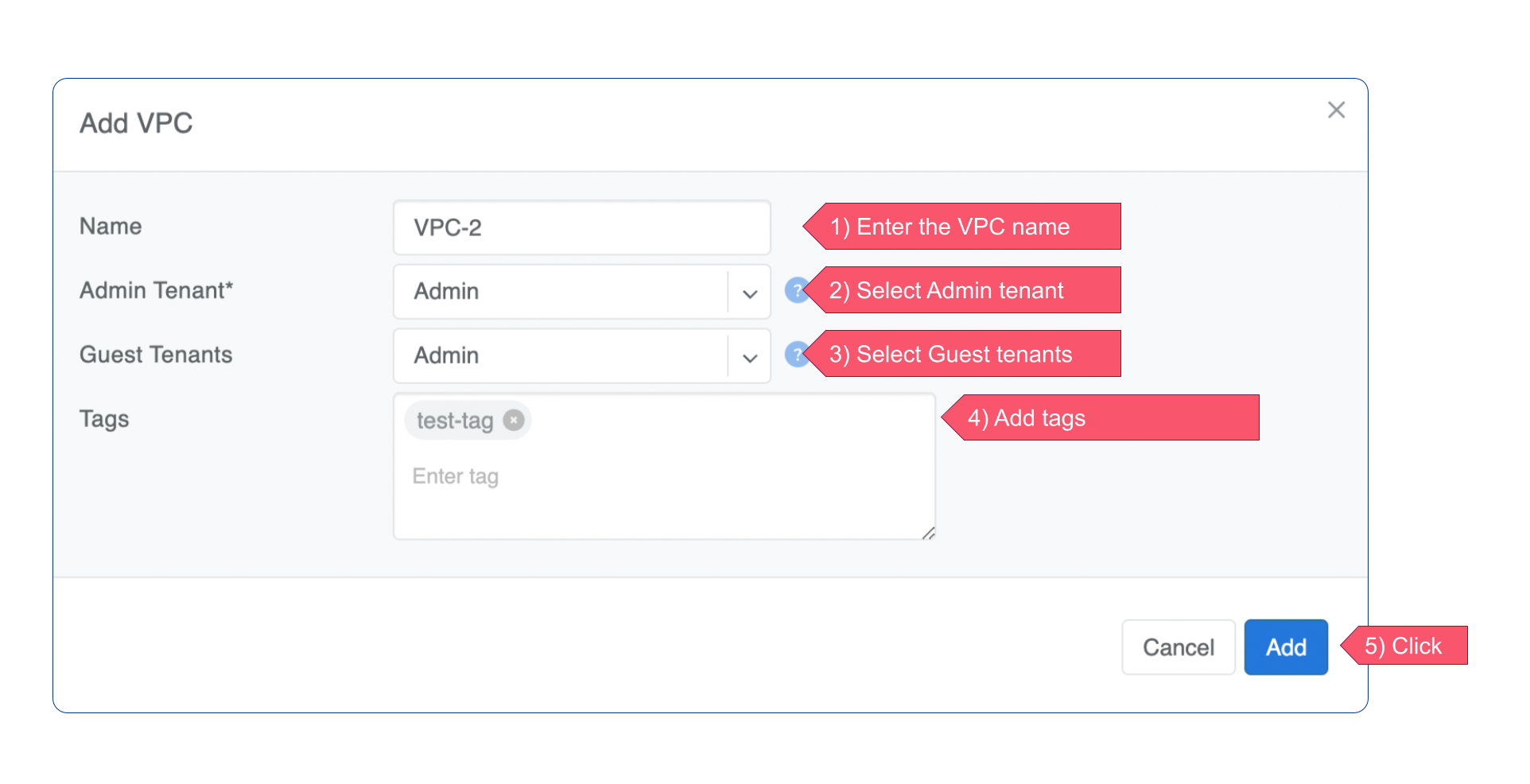
Adding new VPC
Navigate to Network → VPC in the web UI.
Click Add button.
IP Address Management
Netris IPAM allows users to document their IP addresses and track pool usage. It is designed to have a tree-like view to provide opportunity to perform any kind of subnetting.
Purpose: Users define specific roles (purpose) for each subnet/address and only after that are allowed to use those subnets in services like V-Net, NAT, etc…
Each VPC has its own IPAM table.
Allocations and Subnets
There are 2 types of IPAM objects:
Allocations are IP ranges allocated to an organization via RIR/LIR or private IP ranges that are going to be used by the network.
Subnets are prefixes which are going to be used in services. Subnets are always children of allocations. Allocations do not have parent subnets.
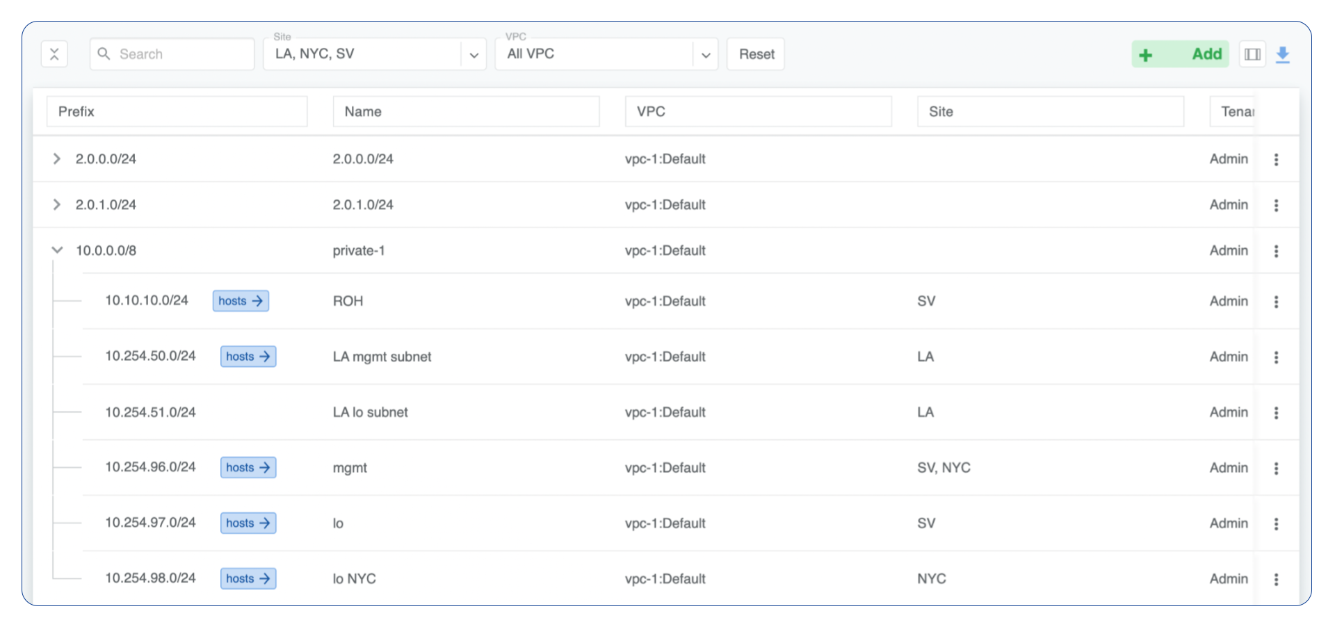
IPAM Tree View
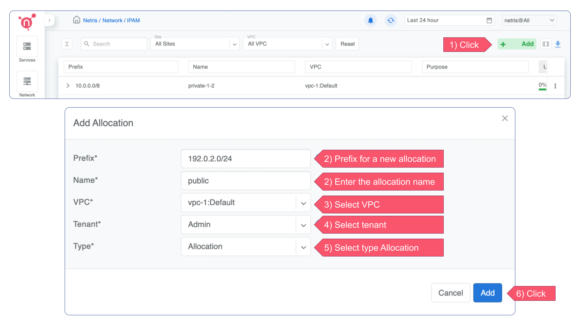
Add an Allocation
Navigate to Network → IPAM
Click the Add button
Select Allocation from the bottom select box
Fill in the rest of the fields based on the requirements listed below
Click the Add button
Prefix |
Unique prefix for allocation, must not overlap with other allocations. |
Name |
Unique name for current allocation. |
VPC |
Select a VPC to which the allocation belongs. |
Tenant |
Owner of the allocation. |
Add a Subnet
Create subnets for devices
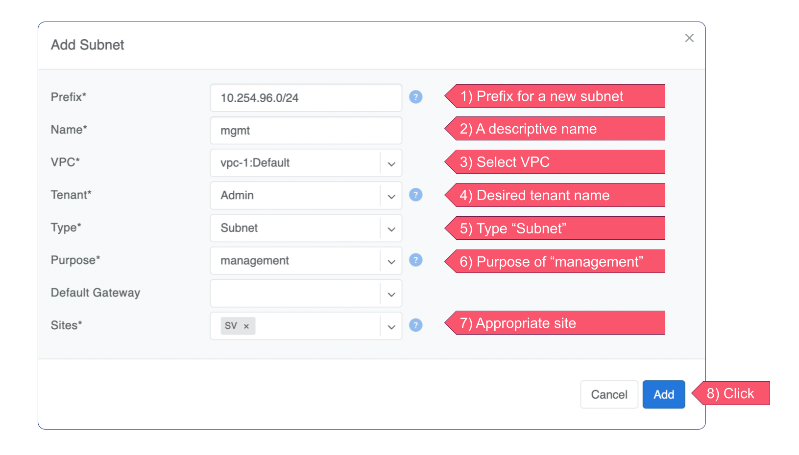
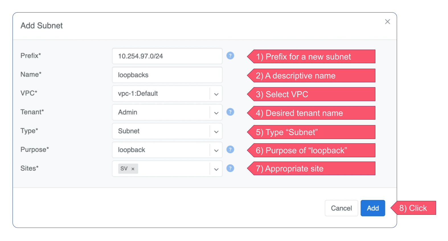
You will require two subnets for your devices: one for loopback IP addresses and another for the management network. Note that device subnets must reside in the System VPC.
Navigate to Network → IPAM
Click the Add button
Select Subnet from the bottom select box
Fill in the rest of the fields based on the requirements listed below
Click the Add button
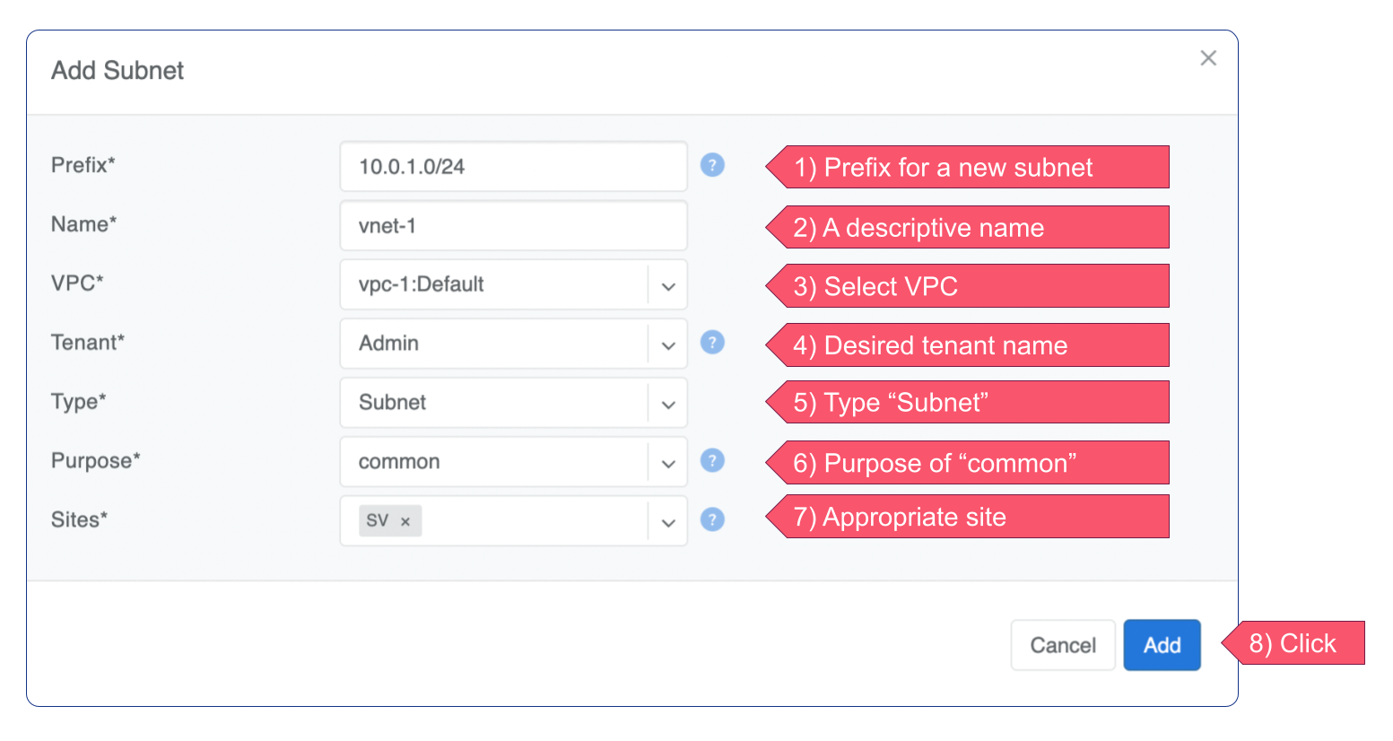
Create subnets for V-Nets
Create at least one subnet with the Common purpose to use it for a new V-Net. IP addresses from this subnet will be assigned to your servers.
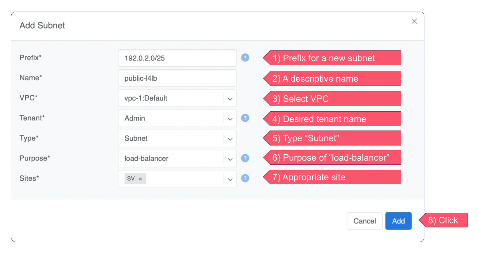
Create subnets for Load-balancing service
Warning
Subnet intended for Load-balancing should be assigned to the system VPC.
If you plan to use load-balancing services, you should first define subnet(s) from which IP addresses will be assigned for Virtual IP (frontend).
Create subnets for NAT service
If you plan to perform network address translation (NAT), you must first create subnets for this purpose.
Warning
Subnet intended for NAT should be assigned to the system VPC.
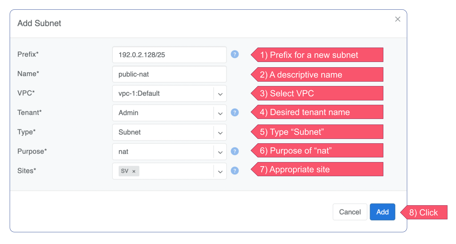
Prefix |
Unique prefix for subnet, must be included in one of allocations. |
Name |
Unique name for current subnet. |
VPC |
Select a VPC to which the subnet belongs. |
Tenant |
Owner of the subnet. |
Purpose |
This field describes for what kind of services the current subnet can be used. It can have the following values:
|
BGP
Basic BGP
BGP neighbors can be declared in the Network → E-BGP section. Netris software will automatically generate and program the network configuration to meet the requirements.
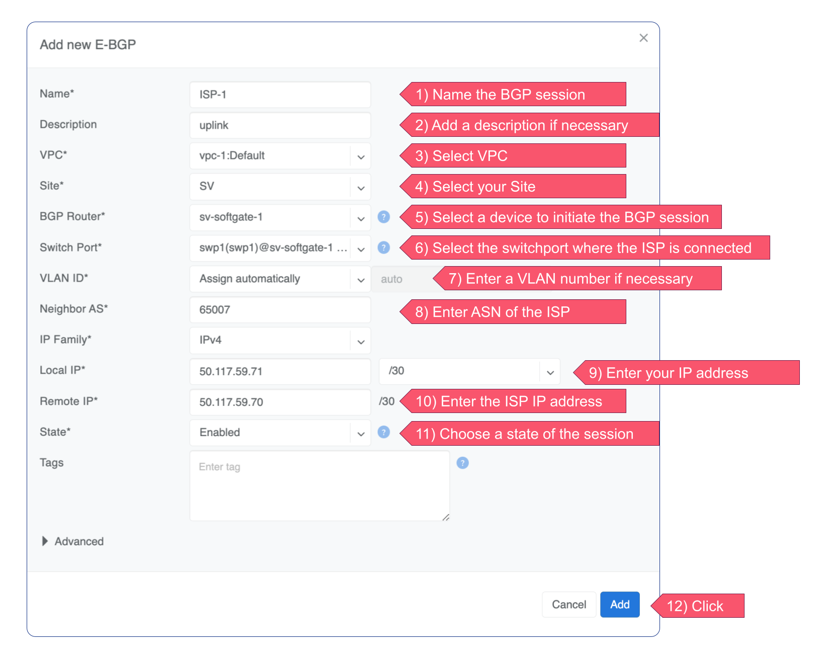
Adding BGP Peers
Navigate to Network → E-BGP in the web UI.
Click the Add button.
Fill in the fields as described in the table below.
Click the Add button.
Name |
User assigned name of BGP session. |
|
Description |
Free description. |
|
VPC |
Select the VPC to which the BGP session should belong. |
|
Site |
Select the site (data center) where this BGP session should be terminated on. |
|
Softgate |
Only if SoftGate nodes are in use. Define on which node BGP session should be terminated on. |
|
Neighbor Autonomous System number of the remote side. (Local AS is defined at Network → Sites section). |
||
Terminate on switch |
Typically used for setups without SoftGate |
specifically for connecting with upstream routers. It instructs the system to terminate the BGP session directly on the switch. |
Switch port |
Switch Port for the physical cable to the BGP neighbor (any port on the fabric). Optionally can be bound to a V-Net service. Typically used for peering with IXPs or systems like GGC (Google Global Cache). |
|
VLAN ID |
Optionally tag with a VLAN ID (usually untagged). |
|
IP Version |
IPv4 or IPv6. |
|
Local IP |
BGP peering IP address on Netris controlled side. |
|
Remote IP |
BGP peering IP address on the remote end. |
|
State |
Administrative state (Enabled/Disabled). |
|
Advanced |
Advanced policy settings are described in the next section. |
|
Tags |
Tags associated with the BGP session. |
Example: Declare a basic BGP neighbor.
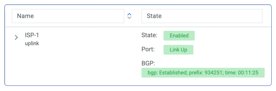
If everything is correct, State, port and BGP will get green status.
Advanced BGP
BGP neighbor declaration can optionally include advanced BGP attributes and BGP route-maps for fine-tuning of BGP policies.
Click Advanced to expand the BGP neighbor add/edit window.
Connect via V-Net |
Select a V-Net if the BGP session is to be established with an endpoint from that V-Net. |
|
BFD |
Enable/Disable BFD. |
|
BGP Timers |
Keepalive Interval |
Hold Time and Connect Retry timers for the BGP session. Netris default values are 3 10 10. |
Neighbor address |
IP address of the neighbor when peering with the loopback IP address instead of the interface IP address (aka Multihop). |
|
Update source |
When Multihop BGP peering is used it allows the operator to choose one of the loopback IP addresses of the SoftGate node as a BGP speaker source IP address. |
|
BGP password |
Password for the BGP session |
|
Allowas-in |
Define the number of allowed occurrences of the self AS number in the received BGP NLRI to consider it valid (normally 0). |
|
Default Originate |
Originate default route to the current neighbor. |
|
Prefix Inbound Max |
Drop the BGP session if the number of received prefixes exceeds this max limit. For switch termination maximum allowed is 1000 prefixes and SoftGate termination can handle up to one million prefixes. |
|
Inbound Route-Map |
Apply BGP policies described in a route-map for inbound BGP updates. |
|
Outbound Route-Map |
Apply BGP policies described in a route-map for outbound BGP updates. |
|
Local Preference |
Set local preference for all inbound routes for the current neighbor. |
|
Weight |
Set weight for all inbound routes for the current neighbor. |
|
Prepend Inbound (times) |
How many times to prepend self AS number for inbound routes. |
|
Prepend Outbound (times) |
How many times to prepend self AS number for outbound routes. |
|
Prefix List Inbound |
List of IP addresses prefixes to permit or deny inbound. |
|
Prefix List Outbound |
List of IP addresses prefixes to permit or deny outbound. |
|
Send BGP Community |
List of BGP communities to send to the current neighbor. |
BGP Objects
IPv4 Prefix
IPv6 Prefix
AS-PATH
Community
Extended Community
Large Community
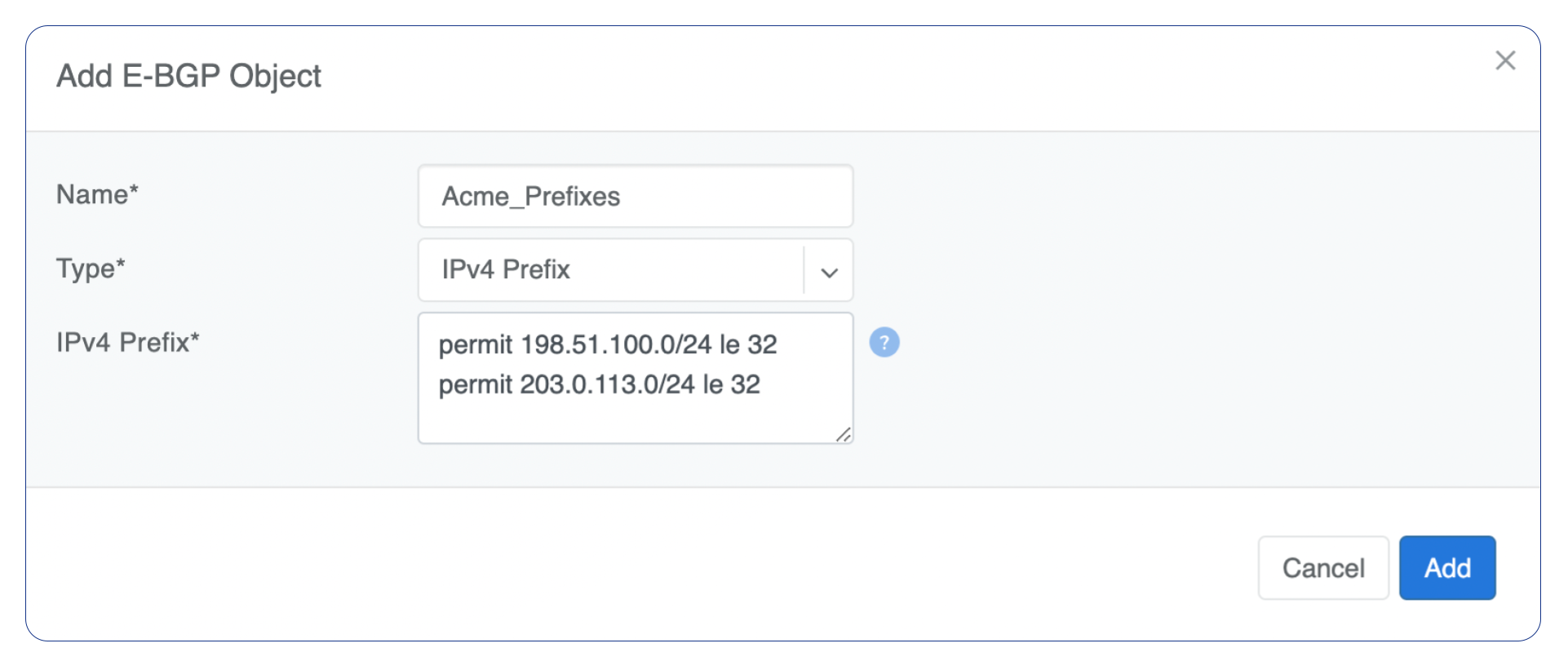
IPv4 Prefix
Action - Possible values are: permit or deny (mandatory).
IP Prefix - Any valid IPv4 prefix (mandatory).
Length - Possible values are: le <len>, ge <len> or ge <len> le <len>.
Example: Creating an IPv4 Prefix list.
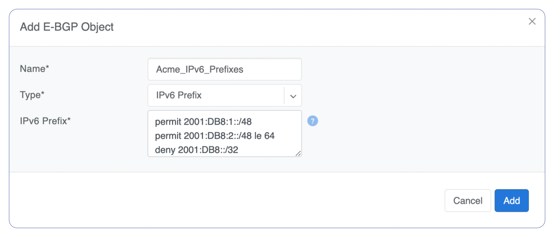
IPv6 Prefix
Action - Possible values are: permit or deny (mandatory).
IP Prefix - Any valid IPv6 prefix (mandatory).
Keyword - Possible values are: le <len>, ge <len> or ge <len> le <len>.
Example: Creating an IPv6 Prefix list.
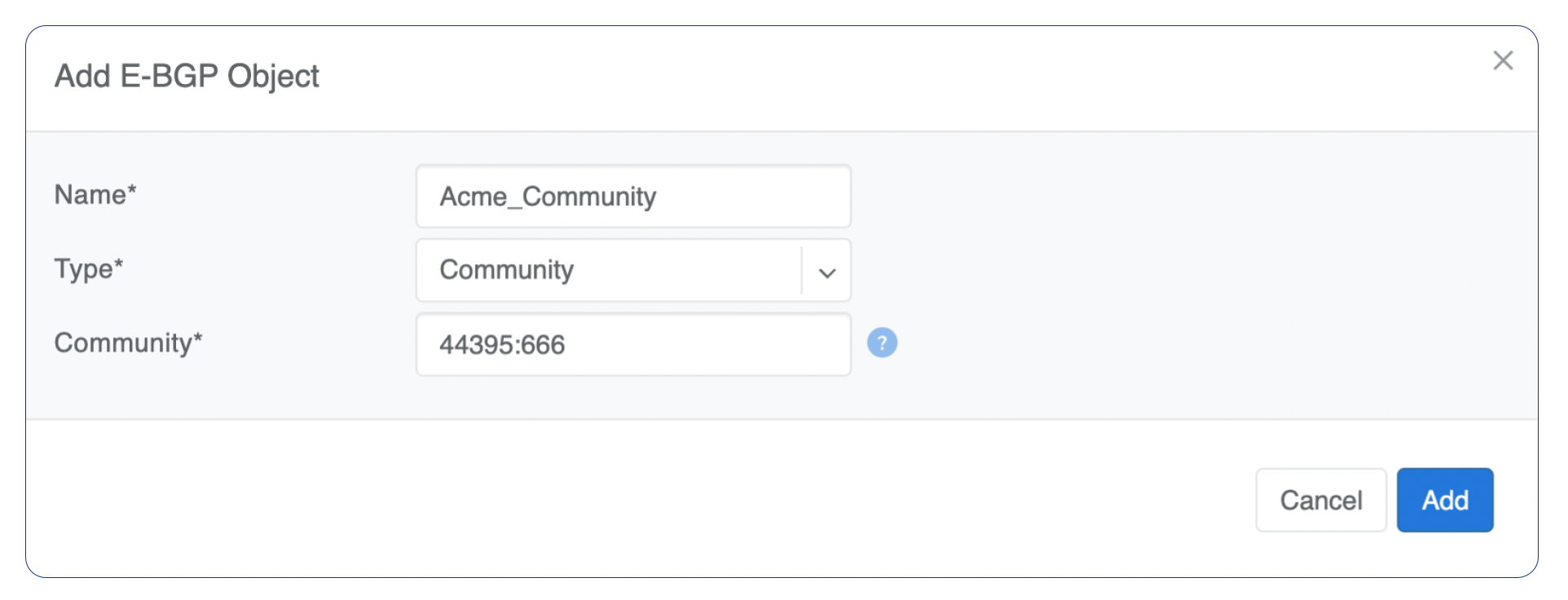
Community
Action - Possible values: permit or deny (mandatory).
Community string - Allowed format:
< permit/deny> LINE. LINE is AA:NN Community number in AA:NN format (where AA and NN are (0-65535)) orlocal-AS,no-advertise,no-export,internetoradditive.
Example: Creating community.
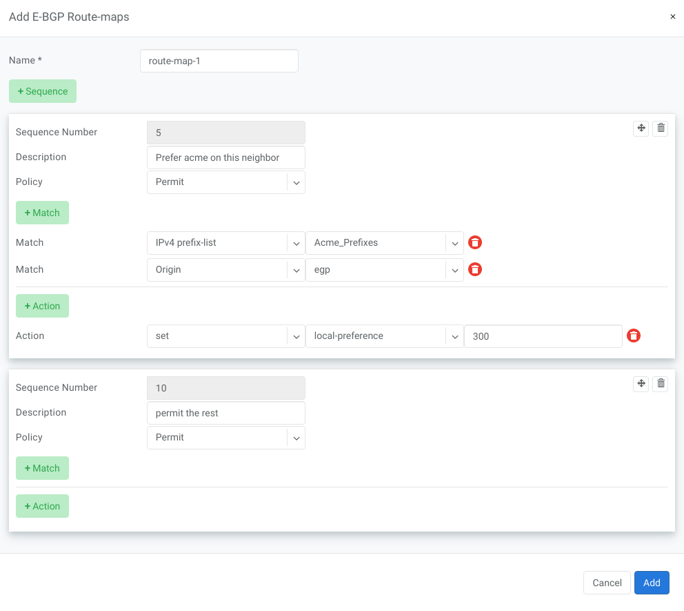
BGP route-maps
Sequence Number - Automatically assigned a sequence number. Drag and move sequences to organize the order.
Description - Free description.
Policy - Permit or deny the routes which match below all match clauses within the current sequence.
Match - Rules for route matching.
Type - Type of the object to match: AS-Path, Community, Extended Community, Large Community, IPv4 prefix-list, IPv4 next-hop, Route Source, IPv6 prefix-list. IPv6 next-hop, local-preference, MED, Origin, Route Tag.
Object - Select an object from the list.
Action - Action when all match clauses are met.
Action type - Define whether to manipulate a particular BGP attribute or go to another sequence.
Attribute - The attribute to be manipulated.
Value - New attribute value.
Example: route-map
eBGP Importing Non-Default Routes into a VPC
In multi-uplink deployments SoftGate Hyperscale (SG-HS) nodes can be eBGP peered with different upstream networks.
By default, Netris SoftGates only redistribute the default route into tenant VPCs, regardless of what other prefixes they receive from upstream peers. This ensures a consistent routing table across all SoftGates, but can lead to suboptimal routing, where traffic from the VPC is always routed to the SoftGate receiving the default, even if another SoftGate has a better path via specific prefixes.
Starting with version 4.5.4, Netris introduces a mechanism to selectively import non-default routes into VPCs by tagging them with a special BGP community: 0:7. Routes marked with this community will be redistributed into tenant VPCs alongside the default.
Warning
Importing additional prefixes into VPCs increases the size of the routing table on SoftGates and switches. Ensure that your hardware can handle the increased load, especially if you plan to import many prefixes.
How to Import Non-Default Prefixes
You have two options for tagging the desired prefixes with the required 0:7 community.
Option 1: Tag Inbound in Netris (on SoftGate HS)
If you manage the eBGP peer configuration using the Netris Controller, you can mark specific routes for redistribution into tenant VPCs by tagging them with the special BGP community 0:7.
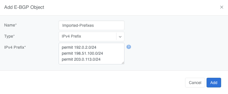
Create a Prefix List under Network → E-BGP Objects
Tip
Do not include 0.0.0.0/0 — it is automatically imported
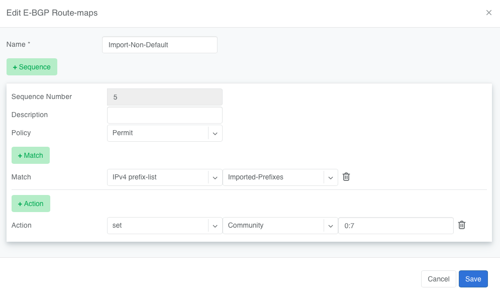
Create a Route Map under Network → E-BGP Route-Maps
Add a new route-map that
Matches the prefix list created in Step 1
Sets the BGP community to
0:7
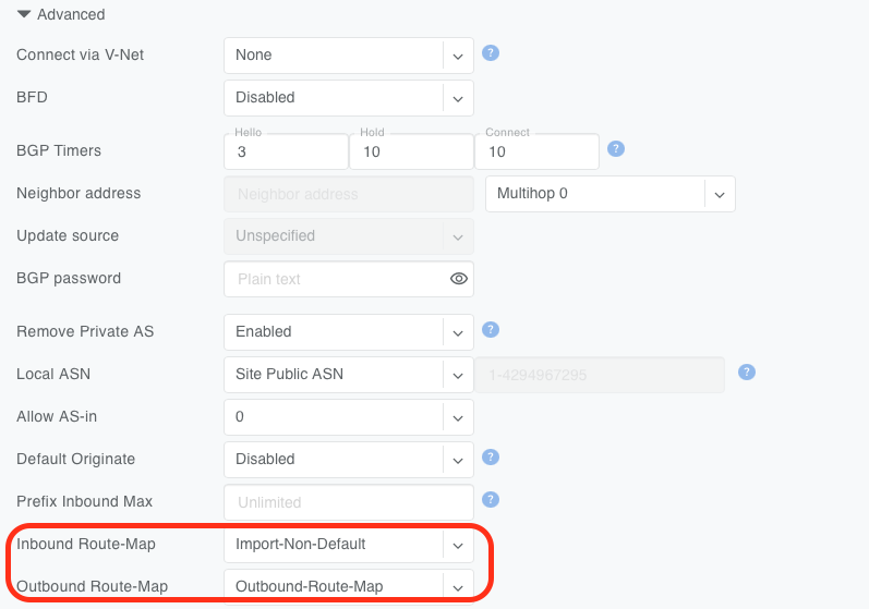
Attach the Route Map to the eBGP Peer under Network → E-BGP
Edit the relevant eBGP neighbor and under Advanced Settings, set the inbound route-map to the one created in Step 2
Once applied, any matching prefixes received from this eBGP peer will be tagged with community 0:7, making them eligible for redistribution into tenant VPCs by the SoftGate.
Tip
You can verify imported routes in the Network → Looking Glass section of the Controller UI.
Warning
When configuring an inbound route-map on an eBGP peer, an outbound route-map must also be set. If no outbound route-map is needed, create a dummy one that permits all routes without modification and attach it to the outbound direction.
Option 2: Tag Outbound from External BGP Peer
Alternatively, the external BGP speaker can set the 0:7 community on outbound updates before advertising routes to the SoftGate. This option does not require any configuration in Netris, as long as the incoming route already carries the community.
This is useful when the upstream router is under the customer’s control and managing policy from that side is preferred.
Static Routing
Located under Network → Routes is a method for describing static routing policies that Netris will dynamically inject on switches and/or SoftGate where appropriate. We recommend using the Routes only if BGP is not supported by the remote end.
Typical use cases for static routing:
To connect the switch fabric to an ISP or upstream router in a situation where BGP and dual-homing are not supported.
Temporary interconnection with the old network for a migration.
Routing a subnet behind a VM hypervisor machine for an internal VM network.
Specifically routing traffic destined to a particular prefix through an Out-of-Band management network.
Add new static route fields description:
Prefix - Route destination to match.
Next-Hop - Traffic destined to the Prefix will be routed towards the Next-Hop. Note that static routes will be injected only on units that have the Next-Hop as a connected network.
Description - Free description.
VPC - Select a VPC to which the static route belongs.
Site - Site where Route belongs.
State - Administrative (enable/disable) state of the Route.
Apply to - Limit the scope to particular units. It’s typically used for Null routes.
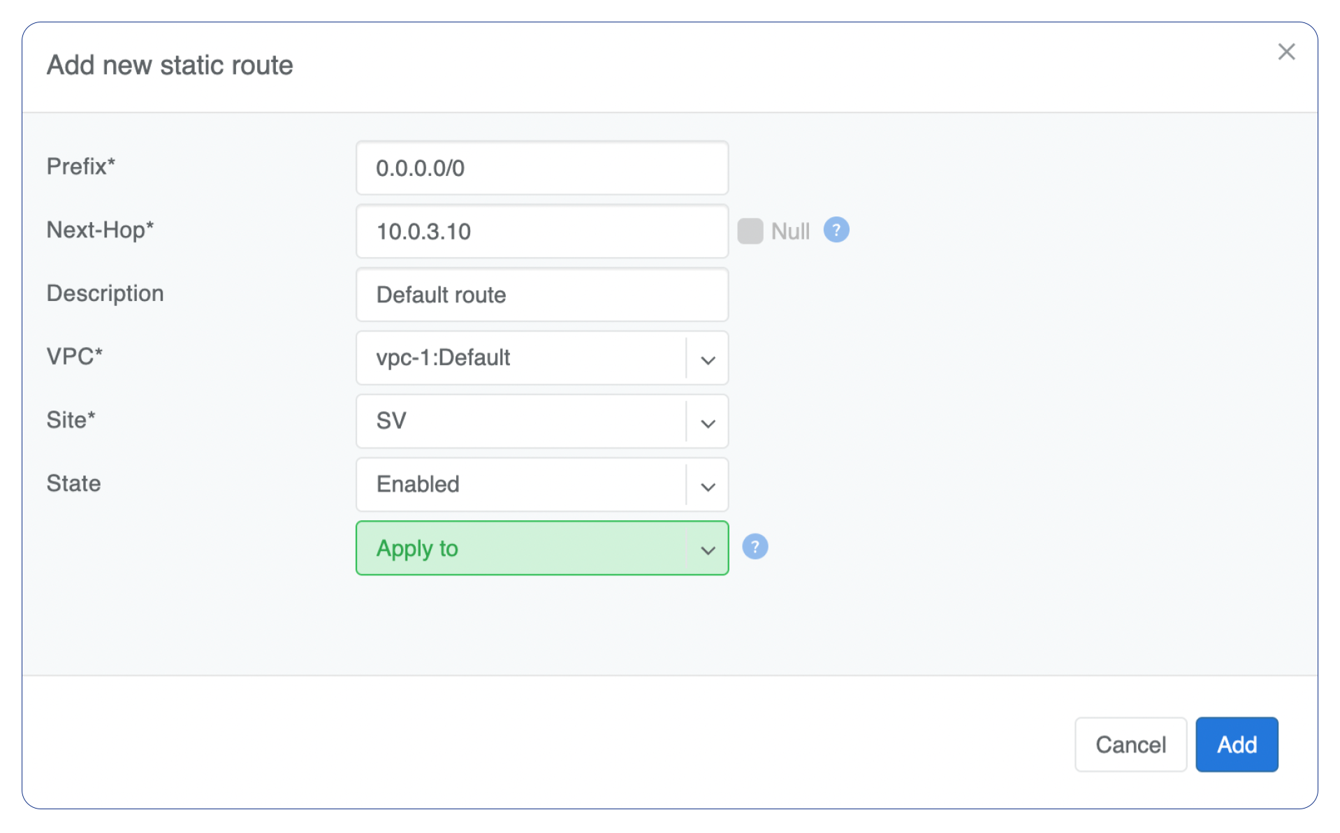
Example: Default route pointing to a Next-Hop that belongs to one of V-Nets.
Example: Adding a back route to 10.254.0.0/16 through an Out-of-Band management network.
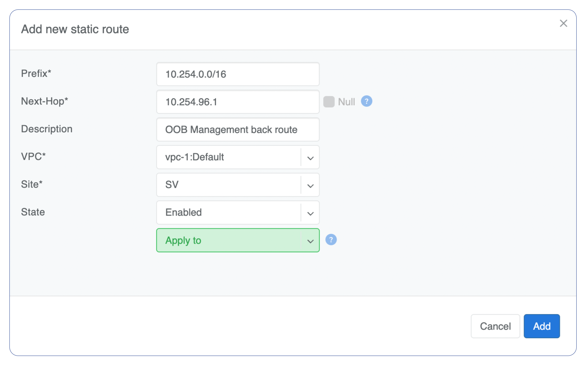
Screenshot shows that the back route is actually applied on Softgate1 and Softgate2 .

NAT
If you utilize private address space for your hosts, you may need a NAT service to enable internet access. Netris SoftGate nodes are required for NAT (Network Address Translation) functionality to work and support SNAT and DNAT features.
Enabling NAT
To enable NAT for a given site, you first need to create a subnet with NAT purpose in the IPAM section. The NAT IP addresses can be used for SNAT or DNAT as a global IP address (the public IP visible on the Internet). NAT IP pools are IP address ranges that SNAT can use as a rolling global IP (for a larger scale, similar to carrier-grade SNAT). SNAT is always overloading the ports, so many local hosts can share one or just a few public IP addresses. You can add as many NAT IP addresses and NAT pools as you need. Adding an IP Subnet under Network → IPAM.
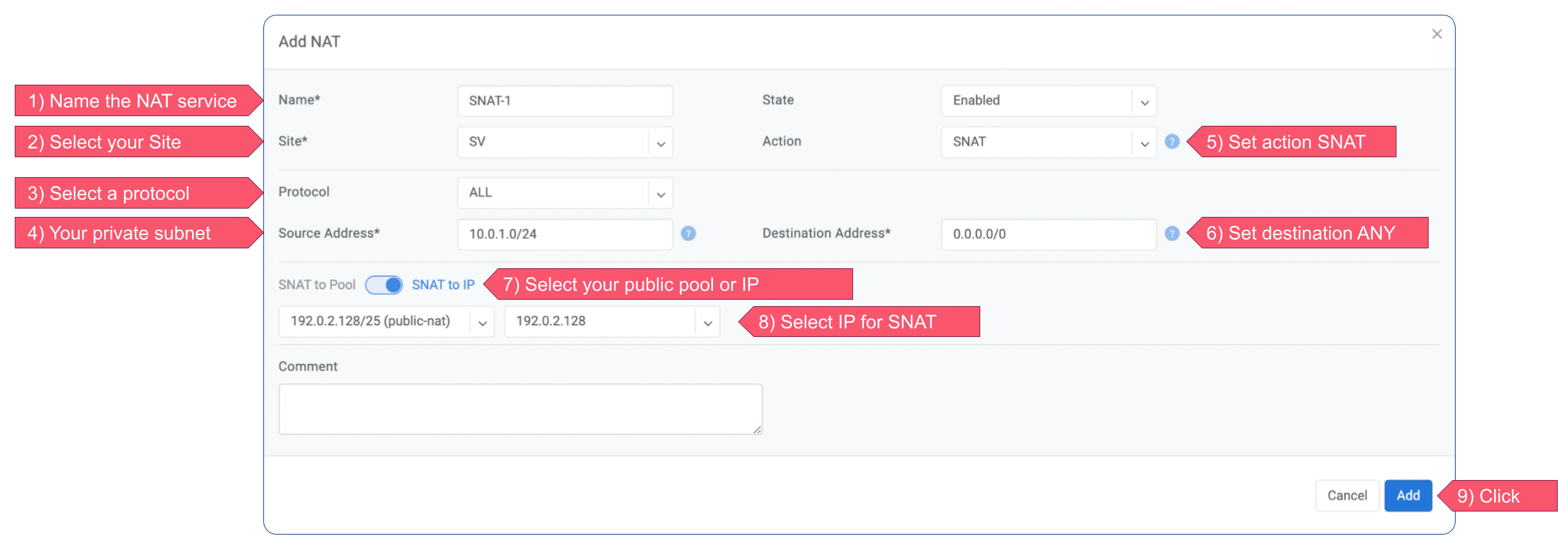
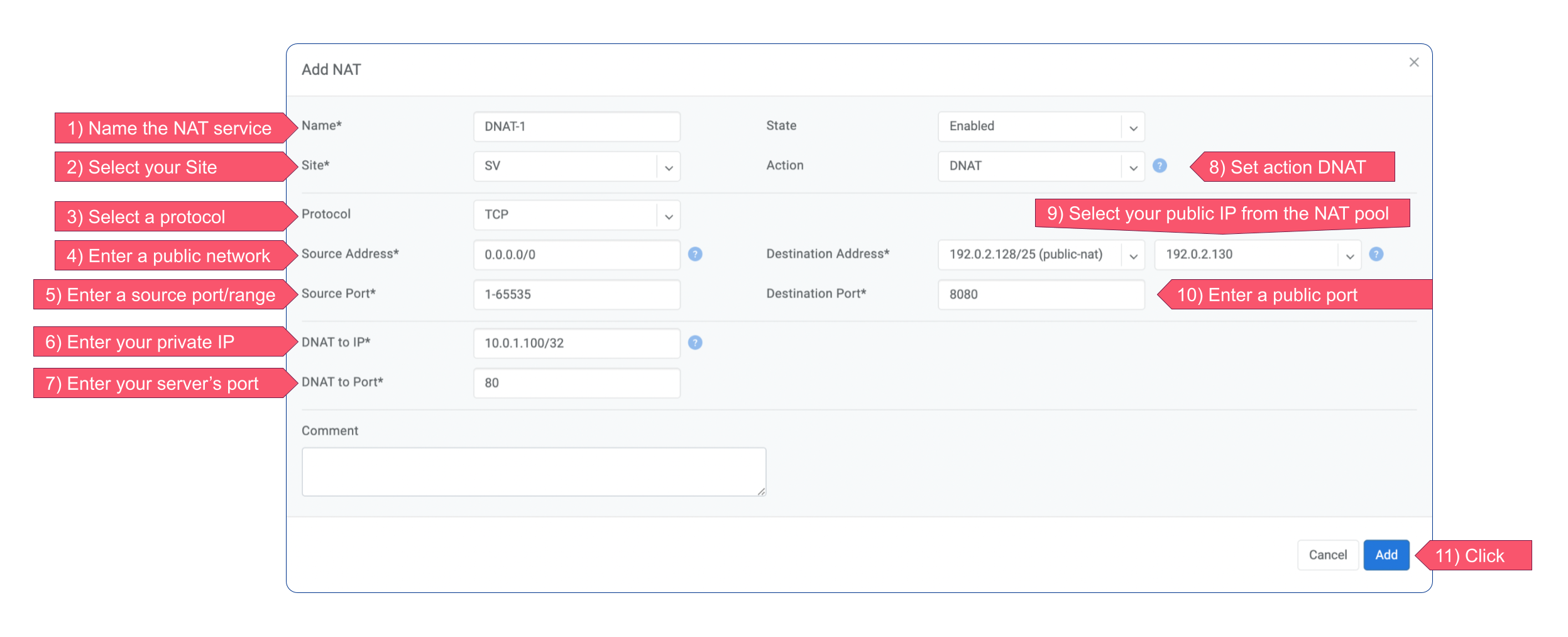
Defining NAT rules
NAT rules are defined under Network → NAT.
Example: SNAT all hosts on 10.0.1.0/24subnet to the Internet using 192.0.2.128as a global IP.
Example: Port forwarding. DNAT the traffic destined to 192.0.2.130:8080 to be forwarded to the host 10.0.1.100 on port tcp/80.
Name |
Unique name. |
|---|---|
State |
State of rule (enabled or disabled). |
Site |
Site to apply the rule. |
Action |
SNAT - Replace the source IP address with specified NAT IP along with port overloading. DNAT - Replace the destination IP address and/or destination port with specified NAT IP. ACCEPT - Silently forward, typically used to add an exclusion to broader SNAT or DNAT rule. |
Protocol |
All - Match any IP protocol. TCP - Match TCP traffic and ports. UDP - Match UDP traffic and ports. ICMP - Match ICMP traffic. |
Source |
Address - Source IP address to match. Port - Source ports range to match with this value (TCP/UDP). |
Destination |
Address - Destination IP address to match. In the case of DNAT it should be one of the predefined NAT IP addresses. Port - For DNAT only, to match a single destination port. Ports - For SNAT/ACCEPT only. Destination ports range to match with this value (TCP/UDP). |
DNAT to IP |
The global IP address for SNAT to be visible on the Public Internet. The internal IP address for DNAT to replace the original destination address with. |
DNAT to Port |
The Port to which destination Port of the packet should be NAT’d. |
Status |
Administrative state (enable/disable). |
Comment |
Free optional comment. |
Looking Glass
The Looking Glass Is a GUI-based tool for looking up routing information from a switch or SoftGate perspective. You can access the Looking Glass either from Topology, individually for every device (right click on device → details → Looking Glass), or by navigating to Network → Looking Glass then selecting the device from the top-left dropdown menu.
Looking Glass controls described for IPv4/IPv6 protocol families.
VPC - select a VPC.
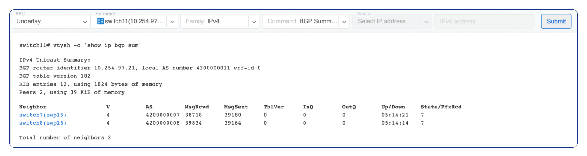
BGP Summary - Shows the summary of BGP adjacencies with neighbors, interface names, prefixes received. You can click on the neighbor name then query for the list of advertised/received prefixes.
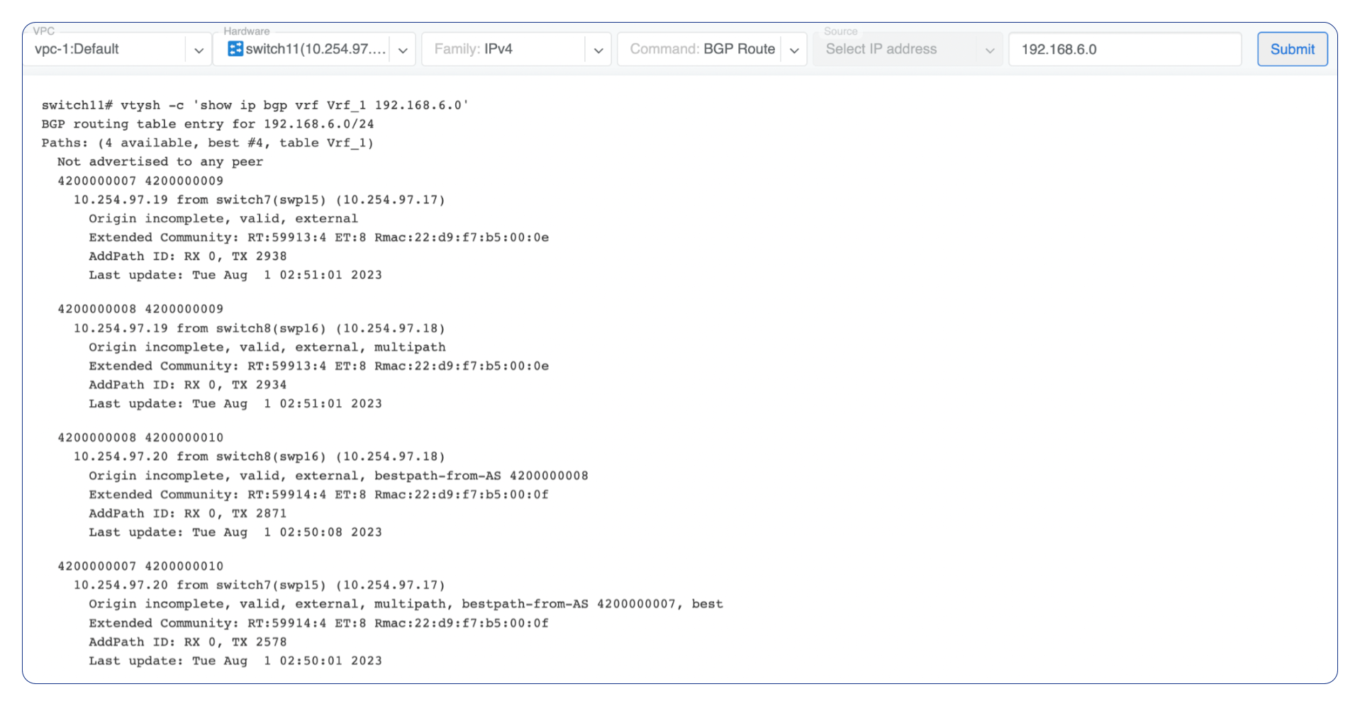
BGP Route - Lookup the BGP table (RIB) for the given address.
Route - Lookup switch routing table for the given address.
Traceroute - Conduct a traceroute from the selected device towards the given destination, optionally allowing to determine the source IP address.
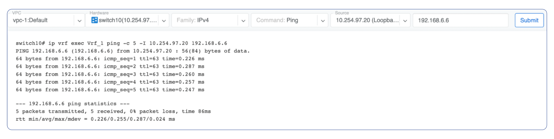
Ping - Execute a ping on the selected device towards the given destination, optionally allowing to select the source IP address.
Example: listing BGP neighbors of a switch and number of received prefixes for the Underlay VPC.
Example: BGP Route - looking up V-Net subnet from switch11 perspective. Switch11 is load balancing between four available paths.
Example: Ping.
VPC - select a VPC.
BGP Summary - Show brief summary of BGP adjacencies with neighbors, interface names, and EVPN prefixes received.
VNI - List VNIs learned.
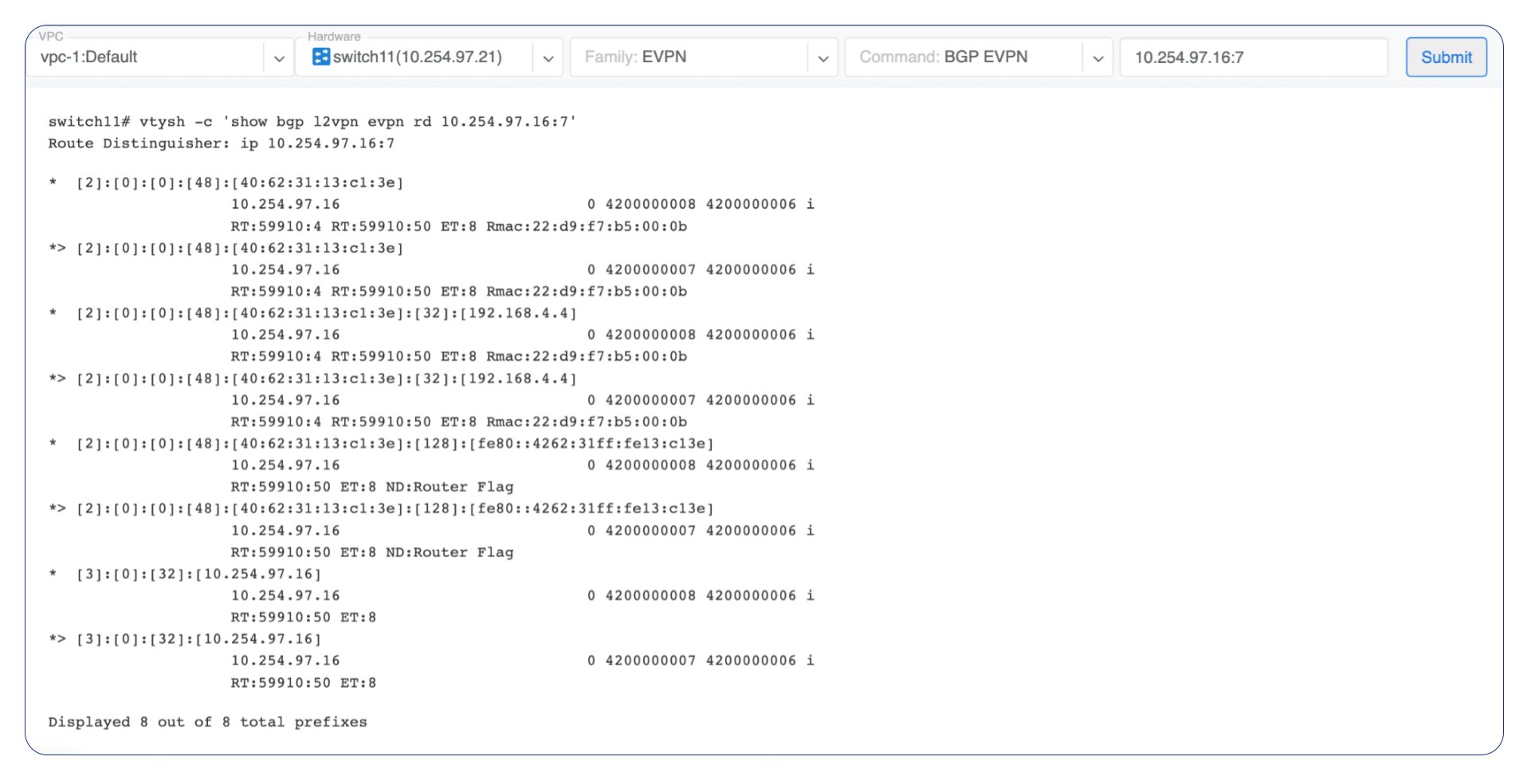
BGP EVPN - List detailed EVPN routing information optionally for the given route distinguisher.
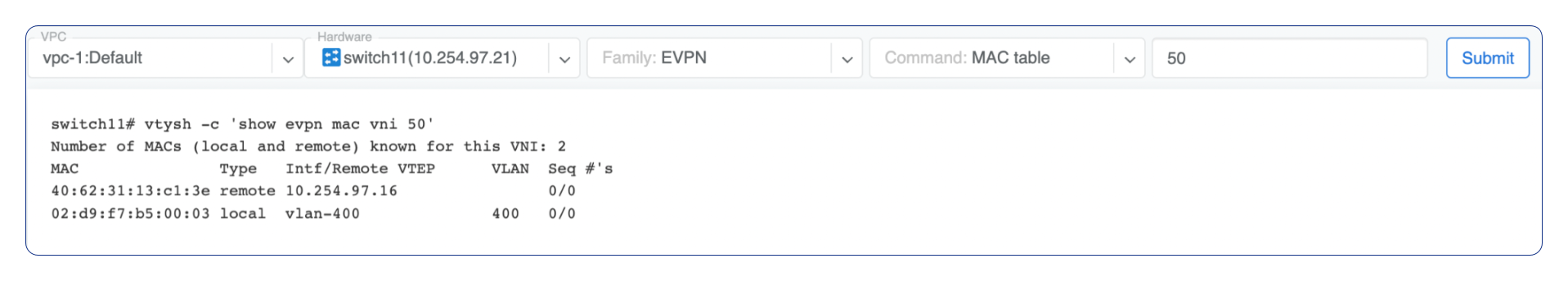
MAC table - List MAC address table for the given VNI.
Example: Listing MAC addresses on VNI 50.
Example: EVPN routing information listing for a specified route distinguisher.
VPC Peering
VPC peering allows routing between two VPCs. It is typically used to connect a tenant VPC to a “shared” VPC where the shared services (like storage access, DNS, etc.) are located.
Consider the following scenario.
Customer VPC A and Customer VPC B accessing common services in a “Shared” VPC via VPC peering.
Customer A and Customer B cannot access each other’s VPCs
Customer A VPC will have routes of the “Shared” VPC, it will NOT have routes of Customer B VPC. Customer B VPC will have routes of the “Shared” VPC, it will NOT have routes of Customer A VPC.
The “Shared” VPC will have routes of both A and B Because A does not have routes of B and vice versa they cannot reach each.
Network Administrators are free to define prefix lists of VPC peering, if VPC A is configured to accept routes of VPC B from the “Shared” VPC, then Customer A can reach Customer B,but if peering is created without defining prefix list (letting netris auto-populate).
Additional details are coming soon…