 Join Slack
BlueField-3 DPU Support in Netris
Overview
Netris supports NVIDIA BlueField-3 Data Processing Units (DPUs) as managed network devices within a server’s inventory. Once registered, a DPU participates in the North-South Ethernet fabric alongside physical switches — establishing BGP EVPN adjacencies, functioning as a VXLAN Tunnel Endpoint (VTEP), and exposing Virtual Functions (VFs) to the host OS as assignable network endpoints.
This allows you to attach a server’s workloads to a VNet through a DPU VF using the same workflow you would use for a physical switch port.
What Is a DPU
A Data Processing Unit is a system-on-a-chip device installed inside a server as a PCIe card. Unlike a standard NIC, a DPU contains its own CPU, memory, and OS, and can run networking services independently of the host.
In DPU mode, a BlueField-3 behaves as an embedded managed switch inside the server. Its two external ports (p0 and p1) uplink to the data center Ethernet fabric. Internally, it exposes a configurable number of Virtual Functions to the host OS. Each VF appears to the host as an independent network interface and can be assigned to a tenant workload.

From the fabric’s perspective, a VF is functionally equivalent to a physical switch port. When switches and DPUs participate in the same EVPN control plane, physical switch ports and DPU VFs can be members of the same VNet — enabling bare-metal and virtualized workloads to share hardware-enforced tenant isolation across both device types.
Netris manages this unified fabric — programming EVPN and VXLAN consistently across switches and DPUs — and exposes both switch ports and DPU VFs through the same VNet attachment workflow.
Prerequisites and Assumptions
Before registering a DPU in Netris, the following conditions must be met.
DPU mode. BlueField-3 ships in DPU mode by default. Netris assumes the DPU is already in DPU mode. Mode switching and OS installation are typically handled by NVIDIA DPF.
Management reachability. The DPU must be reachable on the management network before Netris can communicate with it. Its 1 GbE MGMT port must be physically cabled and accessible. Management connectivity must be established either through an external Out-of-Band network or through a VNet that includes the DPU management port.
Agent installation. Registering a DPU in Netris inventory does not automatically install the Netris agent onto the DPU. Agent installation is handled through DPF.
Use Cases
Single-tenant server, North-South connectivity via DPU. The most common deployment. One DPU per server. The DPU’s two uplink ports connect to leaf switches. For a single-tenant server, it may be more appropriate to expose a Physical Function (PF) interface directly to the host OS rather than a VF, reducing overhead and simplifying the data path. All North-South traffic passes through the DPU rather than a direct switch port. The DPU handles BGP and VXLAN on behalf of the host.
Concurrent multi-tenancy on a shared server. Multiple tenants share a single physical server. Each tenant’s workload binds to one or more VFs. The DPU enforces isolation between tenants in hardware, offloading this function from the host CPU. Netris assigns each VF to the appropriate tenant VNet. This enables hardware-accelerated multi-tenancy without software overhead on the North-South datapath.
Mixed endpoints in a single VNet. A VNet can include both physical switch ports (for bare-metal servers connected directly to the fabric) and DPU VFs (for workloads running on DPU-equipped servers). Netris coordinates EVPN and VXLAN configuration across both device types so that all endpoints share the same tenant network with consistent hardware-enforced isolation.
Configuring a Server with a DPU
For step-by-step instructions on adding a DPU to a server object in Netris inventory, see Adding DPUs.
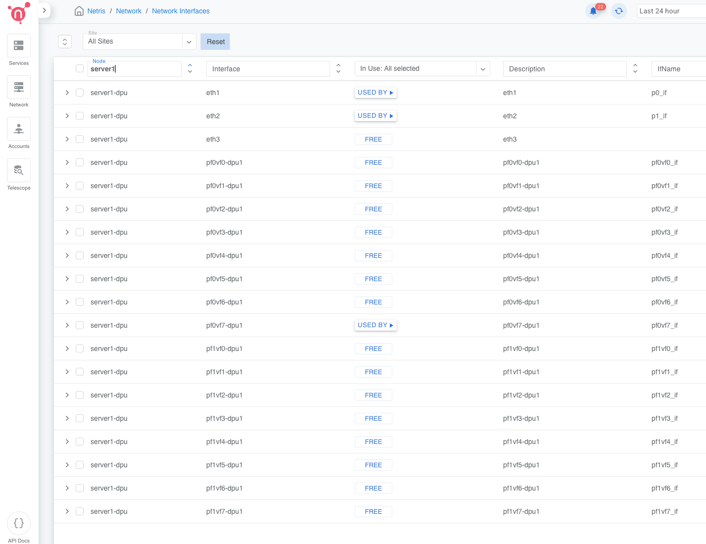
VF Interface Naming
After save, Netris generates VF interface objects for each DPU based on the port count and VF count configured.
For a DPU with two physical ports and X number of Virtual Functions total, VFs are split evenly between the two physical functions:
pf0vf0-dpu1 through pf0vf(X/2-1)-dpu1
pf1vf0-dpu1 through pf1vf(X/2-1)-dpu1
For a DPU with one physical port and N VFs:
pf0vf0-dpu1 through pf0vf(N-1)-dpu1
The suffix -dpu1 corresponds to the DPU’s index within the server object. A second DPU in
the same server would produce -dpu2, and so on.
Physical uplink ports appear in the interface list as the ethX names they were mapped to. Auto-generated descriptions are injected if the description field is empty (for example, “DPU 1 port 1”, “DPU 1 MGMT”, “DPU 1 pf0vf0”). These descriptions are editable.
Connecting DPU VFs to a VNet
Once the DPU is saved and the agent is installed and reporting, its VF interfaces are available as endpoints in the VNet attach workflow — in the same selector as physical switch ports.
To attach a VF to a VNet, open the target VNet, add a port, and select the VF by name (for
example, pf0vf3-dpu1@servername). The selector supports the same checkbox and label-picker
interaction used for switch ports.
To bulk-assign multiple VFs to a VNet, use labels. Assign a label to the VFs you want to group, then select by label in the VNet port selector.
To add both a physical switch port and a DPU VF to the same VNet, add each as a separate port entry. Netris programs EVPN and VXLAN consistently across both device types, so both endpoints participate in the same tenant network with hardware-enforced isolation.
For full VNet configuration instructions, see V-Net.
Monitoring
DPU health and heartbeat are surfaced in the Inventory view as child status indicators under the parent server.
Heartbeat — reflects connectivity between the Netris controller and the DPU agent. Displayed per DPU. The count shown (for example, OK (2)) represents the number of DPUs in that server with that heartbeat status.
Health checks — aggregated across all DPUs in the server. The total count across OK, Warn, and Crit equals the combined number of health checks for all DPUs in the server.
DPU names appear in the dpuX@hostname format in the Dashboard Agent Heartbeats view (for example, dpu1@hgx-pod00-su0-h01). DPU health monitors are included in the Managed HW Health dashboard view.
Expanding the server row in Inventory shows a per-DPU section with loopback IP, MGMT IP, heartbeat state, aggregated health check counts, and a three-dot menu with options for Network Interfaces and Install Agent.
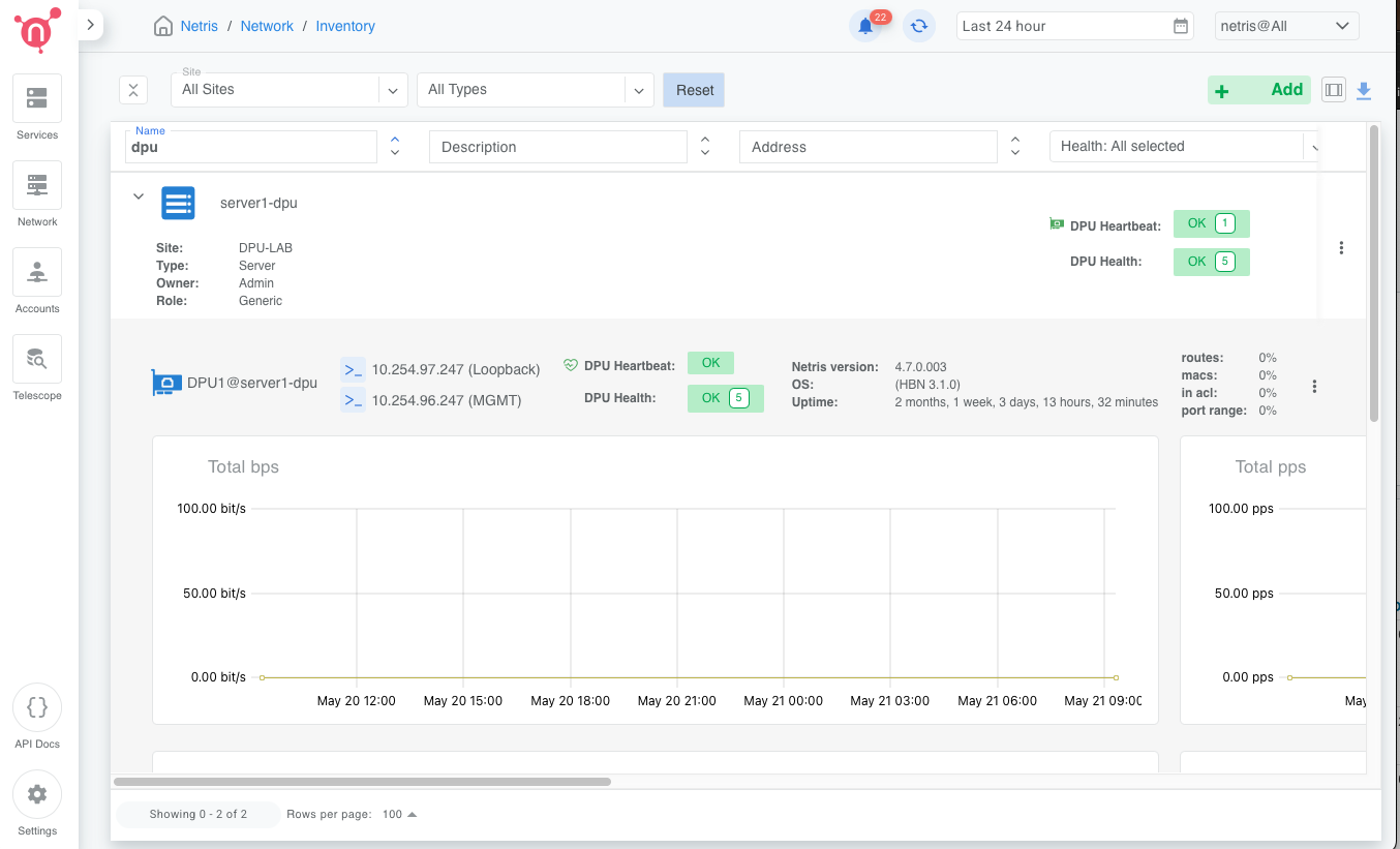
Figure: DPU health status in Inventory view
Warning
Port mappings and VF count cannot be modified after the server object is saved. To change them, delete and recreate the server object.
Warning
Reducing the DPU count on an existing server removes all configuration and VF interfaces associated with the removed DPU blocks. This action cannot be undone.
Warning
Netris does not manage DPU OS installation, firmware updates, or mode switching. These are handled through NVIDIA DPF.